Mistake Analysis in Power Transmission Lines utilizing Elliptical Behaviour of System Parameters
Abstraction—Power transmittal lines which form the anchor of the electrical power system may be subjected to assorted mistakes. The demand of the hr is to observe and sort the mistakes every bit rapidly as possible to guarantee quality uninterrupted power supply. This paper discusses a simple theoretical account to observe and sort mistakes based on the egg-shaped behaviour of the system. The theoretical account based on MATLAB, is user friendly even to unskilled workers.
Keywords— mistake, transmittal lines, mistake types, mistake sensing
I. Introduction
In a 3 stage transmittal line, mistakes may happen at any clip. The causes of mistakes may be environmental or semisynthetic. Mistakes are loosely classified into series and shunt mistakes. A series mistake denotes the unfastened circuit status. Shunt mistakes are of assorted types based on how many lines are affected.
Initially the technique of mistake location was based on the use of synchronised electromotive force measurings at the sending and having terminal [ 1 ] . The method was applied to both transposed and untransposed lines. It reduced many mistakes in mistake analysis.
To better the mistake sensing distinct ripple transform and unreal nervous webs were used [ 2 ] . The nervous webs were trained utilizing MATLAB and daubechies ripple was used. The preparation clip was less in this method but was complicated. Another fresh method discussed mistake categorization based on initial current going moving ridge [ 3 ] . Wavelet transform was adopted to pull out the going moving ridge from station mistake signals.
Following this, mistake analysis methods utilizing fault-feature extraction were used [ 4 ] . Besides delays were introduced to mensurate post-fault values of system parametric quantities. Mistake surveies were done in transformers besides [ 5 ] . Voltage current venue diagram was constructed and based on image processing techniques, mistakes were classified.
New methods of mistake sensing use two-end nonsynchronous measurings of the line and the advantages are the usage of digital engineering and numerical relaying [ 6 ] . The new method does non depend on mistake opposition, beginning electric resistances and pre-fault currents.
Similar to the mistake analysis in transformers discussed above, mistake categorization in transmittal lines can be done [ 7 ] . The method uses wavelet transform and egg-shaped behaviour of the system.
The above discussed methods involve complicated analysis and calculation in assorted signifiers. The mistake sensing mechanism should be user friendly and be every bit simple as possible. Hence, it is concluded that it is necessary to develop a simplified method to observe and sort mistakes in transmittal lines.
When the mistakes are detected and classified beforehand, it becomes easy for the individuals to rectify it within a short period of clip. This paper discusses a simple technique to observe and sort mistakes. The venue of the electromotive force and current signifiers an oval. Using the oval belongingss we can reason if a mistake has occurred or non and sort it.
II. ELLIPTICAL BEHAVIOUR
Voltage and current in the transmittal line may be taken as:
V ( T ) = V
mwickedness ( ?t ) ( 1 )
I ( T ) = I
mwickedness ( ?t- ? ) ( 2 )
Where, V
mand I
mare the peak values, ?=2?f, cos ? is the power factor.
The venue of the electromotive force and current signifiers an oval. The chief belongings of the oval taken for the mistake analysis is the eccentricity. As the eccentricity varies the oval size and country besides varies.
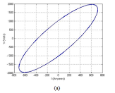
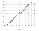
Fig.1. Elliptical venue of electromotive force and current in a transmittal line with eccentricities ( a ) 0.9612, ( B ) 0.9994
III. Working
The proposed theoretical account takes in electromotive force and current values and plots the oval. This oval is compared with the healthy oval on footing of eccentricity. When the eccentricity of the current oval ( Tocopherol
C) does non lie in the scope of healthy oval eccentricity ( Tocopherol
Hydrogen) so a mistake is said to hold occurred.
The oval is once more compared with pre-defined oval for assorted mistakes to obtain values as given in Table.1
From this tabular array mistake categorization is done and the consequence is displayed.
In the tabular array values are assigned to all stages to observe multiple mistakes besides.
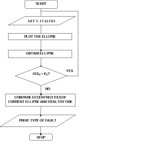
Table.1. Look-up tabular array for mistake categorization
| FAULT IN EACH PHASE |
Type OF FAULT |
| Phase 1 |
Phase 2 |
Phase 3 |
| 0 |
0 |
0 |
Normal status |
| 1 |
1 |
0 |
12 LL |
| 0 |
1 |
1 |
23 LL |
| 1 |
0 |
1 |
13 LL |
| 2 |
0 |
0 |
1-G SLG |
| 0 |
2 |
0 |
2-G SLG |
| 0 |
0 |
2 |
3-G SLG |
| 2 |
2 |
0 |
12-G DLG |
| 0 |
2 |
2 |
23-G DLG |
| 2 |
0 |
2 |
13-G DLG |
| 2 |
2 |
2 |
123 BTP |
| 3 |
0 |
0 |
1 OC |
| 0 |
3 |
0 |
2 OC |
| 0 |
0 |
3 |
3 OC |
| 3 |
3 |
0 |
1,2 OC |
| 0 |
3 |
3 |
2,3 OC |
| 3 |
0 |
3 |
1,3 OC |
| 3 |
3 |
3 |
1,2,3 OC |
|
|
|
|
This look up table aid to sort Single line to land mistake ( SLG ) , Line to line mistake ( LL ) , dual line to land mistake ( DLG ) , Balanced three stage mistake ( BTP ) and unfastened circuit mistake ( OC ) .
III. SIMULATION RESULTS
The construction of the resulting eclipsiss are given below:
A. Single line to land mistake
A individual line to land mistake has occured in stage 2 while the other stages are healthy as shown in Fig.3.

Fig.3. Single line to land mistake
B. Line to line mistake
A line to line mistake has occured in stages 2 and 3 while the other stage is healthy as shown in Fig.4.
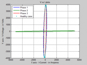
Fig.4. Line to line mistake
C. Double line to land mistake
A dual line to land mistake has occured in stages 1 and 2 while the other stage is healthy as shown in Fig.5.
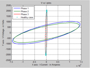
Fig.5. Double line to land mistake
D. Balanced three stage mistake
A Balanced three stage mistake has occured in the line as shown in Fig.6.

Fig.6. Balanced three stage mistake
E. Open circuit mistake
Open circuit mistake has occured in the line as shown in Fig.7.
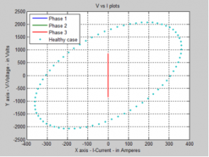
Fig.7. Open circuit mistake
V. CONCLUSION
The advantage of the proposed theoretical account is that it is really simple to implement. It is based on a mathematical background and is less complex. Presents, happenings of mistakes have increased. Hence it is really of import to observe and rectify the mistakes every bit shortly as possible.
Mentions
[ 1 ] Sukumar M. Brahma and Adly A. Girgis ( 2004 ) ‘
Fault Location on a Transmission Line Using Synchronized Voltage Measurements’ , IEEE trans. , power del.
,vol 19, no. 4.
[ 2 ] Chiradeja P. and Ngaopitakkul A. , ( 2009 )
,‘
Designation of Fault Types for Single Circuit Transmission Line utilizing Discrete Wavelet transform and Artificial Neural Networks’ , Intl. MultiConf. of Engineers and Computer Scientists vol II.
[ 3 ] Xinzhou Dong
,Wei Kong and Tao Cui, ( 2009 )
‘Fault Classification and Faulted-Phase Selection Based on the Initial Current Traveling Wave’ , IEEE trans. , power del. , , vol. 24, no. 2.
[ 4 ] Yusuff A.A, Jimoh A.A and Munda J.L, ( 2011 ) ‘
Determinant-based characteristic extraction for mistake sensing and categorization for power transmittal lines’ , IET Gen. , Trans. , Distr.
[ 5 ] Abu-Siada and Syed Islam, ( 2012 )
’A Novel Online Technique to Detect Power Transformer Winding Faults’ , IEEEtrans. Power del
. ,vol 27, no. 2.
[ 6 ] Dine Mohamed, Sayah Houari, Bouthiba Tahar, ( 2012 ) ‘
Accurate Fault Location Algorithm on Power Transmission Lines with usage of Two-end Unsynchronized Measurements’ , Serbian Journal of Elec. Engg. , vol. 9, no. 2, pp. 189-200.
[ 7 ] Andre de Souza Gomes, Marcelo Azevedo Costa, Thomaz Giovani Akar de Faria, and Walmir Matos Caminhas, ( 2013 ) ’
Detection and Classification of Faults in Power Transmission Lines Using Functional Analysis and Computational Intelligence’ , in IEEE trans. Power Del. , vol. 28, no. 3.
