Chapter 4
PROPOSED TECHNIQUE FOR SIDELOBES SUPPRESSION
As seen in old chapters, there are many sidelobes suppression techniques proposed but most of these proposed sidelobe suppression techniques are non good balanced between the complexness and public presentation. The available techniques have their ain advantages and disadvantages in footings of design, execution or may impact the other factors which consequences in hapless overall efficiency.
So in this thesis work we are suggesting Correlative cryptography as another sidelobes one of the suppression method which can be utilized for cut downing the sidelobes power significantly. Before that, allow us see some basic thought about correlativity cryptography.
So far, we have considered the inter symbol intervention as an inauspicious happening which produces a debasement in the system public presentation. Undeniably, its name itself describes a nuisance consequence.
However, by adding inter symbol intervention to the familial signal in a controlled or known mode, it is possible to accomplish a spot rate of 2B0spots per second in a channel of bandwidth B0Hz. These techniques are calledcorrelate cryptographyorpartial-responsesignaling techniques. Since, correlate cryptography strategy is based on the sum of ISI introduced into familial signal. So, the sum of ISI in familial signal is known. The consequence of this ISI can be compensated at the receiving system from the known measure of the ISI.
- Duobinary signaling
The basic thought of correlate cryptography will now be illustrated by sing the specific illustration of duobinary signaling, where “duo” implies duplicating of the transmittal capacity of a consecutive double star system. See a binary input sequence { BK} dwelling of uncorrelated binary figures each holding continuance TBseconds, with symbol 1 represented by a pulsation of amplitude +1 V, and symbol O by a pulsation of amplitude -1 V. When this sequence is applied to a duobinary encoder, it is converted into three-level end product, viz. , -2, 0 and +2 Vs. To bring forth this transmutation, we may utilize the strategy shown in figure 4.1.


Figure 4.1: Duobinary signaling strategy.
The binary sequence { BK} is first passed through a simple filter affecting a individual hold component. For every unit impulse applied to the input of this filter, we get two unit impulse spaced TBseconds apart at the filter end product. We may therefore show the figure degree CelsiusKat duobinary programmer end product as the amount of the present binary figure BKand its old value Bk-1, as shown by
CK=bK+bk-1-- -- -- -- -- -- - ( 17 )
One of the effects of the transmutation describe by ( 17 ) is to alter the input sequence { BK} of uncorrelated binary figures into a sequence { degree CelsiusK} of correlative figures. This correlativity between the next familial degrees may be viewed as presenting intersymbol intervention into the familial signal in an unreal mode.
However, this inter symbol intervention is under the designer’s control, which is the footing of correlate cryptography. An ideal hold component, bring forthing a hold of TBseconds, has the transportation map exp ( -j2?fTB) , so that the transportation map of the simple filter shown in figure 18 is 1+exp ( -j2?fTB) . Hence, the overall transportation map of this filter connected in cascade with the ideal channel Hydrogendegree Celsiuss( degree Fahrenheit ) is
H ( degree Fahrenheit ) = Hdegree Celsiuss( degree Fahrenheit ) [ 1+ exp ( -j2?fTB) ]
= Hdegree Celsiuss( degree Fahrenheit ) [ exp ( j?fTB) + exp ( - j?fTB) ] exp ( -j?fTB)
= 2 Hdegree Celsiuss( degree Fahrenheit ) cos ( ?fTB) exp ( - j?fTB )-- -- -- -- -- -- ( 18 )
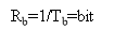
For an ideal channel of bandwidth B0=RB/2, we have
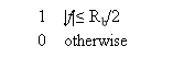

Hydrogendegree Celsiuss( degree Fahrenheit ) = -- -- -- -- -- -- - ( 19 )
Therefore the overall frequence response has the signifier of a half-cycle cosine map, as shown by
Hydrogendegree Celsiuss( degree Fahrenheit ) =
-- -- -- -- -- -- - ( 20 )
For which the amplitude response and stage response are as shown in figure 4.2 ( a ) and figure 4.2 ( B ) , severally. An advantage of this frequence response is that it can be easy approximated in pattern.


Figure 4.2: frequence response of duobinary transition filter
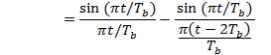
The corresponding value of the impulse response consists of two sinc pulsations, clip displayed by TBseconds, as shown by ( except for a scaling factor )
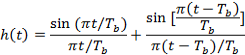
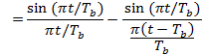
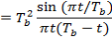 -- -- -- -- -- - ( 21 )
 Which is shown aforethought in figure 4.3.We see that the overall impulse response H ( T ) has merely two distinguishable value at the trying blink of an eyes.


Figure 4.3: Impulse response of duobinary transition filter.
The original informations { BK} may be detected from the duobinary-coded sequence { degree CelsiusK} by deducting the old decoded binary figure from the presently received digit degree CelsiussKin conformity with equation ( 17 ) . Specifically, allowing bI‚Kstand for the estimation of the original binary figure BKas conceived by the receiving system at clip t equal to kTB, we have
bI‚K= cK- bI‚k-1-- -- -- -- -- -- ( 22 )
It is evident that if degree CelsiussKis received without mistake and if besides the old estimation bI‚k-1at clip t= ( k-1 ) ThymineBcorresponds to a right determination, so the current estimation bI‚Kwill be right excessively. The technique of utilizing a stored estimation of the old symbol is called determination feedback.
We observe that the sensing process merely described is basically an opposite of the operation of the simple filter at the sender. However, a drawback of this sensing procedure is that one time mistakes are made, they tend to propagate. This is due to the fact that a determination on the current binary figure BKdepends on the rightness of the determination made on the old binary figure Bk-1.
A practical agency of avoiding this mistake extension is to utilize precoding before the duobinary cryptography, as shown in fig 6.11. The precoding operation performed on the input binary sequence { BK} converts it into another binary sequence { aK} defined by
aK= BK+ ak-1modulo-2 -- -- -- -- -- - ( 23 )
Modulo-2 add-on is tantamount to the exclusive-or operation. An exclusive-or gate operates as follows. The end product of an exclusive-or gate is a 1 if precisely one input is a 1: otherwise, the end product is a 0. The ensuing precoder end product { aK} is following applied to the duobinary programmer, thereby bring forthing the sequence { degree CelsiusK} that is related to { aK} as follows:
degree CelsiussK= aK+ ak-1-- -- -- -- -- ( 24 )
Note that unlike the line drive operation of duobinary cryptography, the precoding is a nonlinear operation. We assume that symbol 1 at the precoder end product in figure 4.4 is represented by +1 V and symbol 0 by -1 V.


Figure 4.4: A precoded duobinary strategy.
Therefore, from equation ( 22 ) and ( 23 ) , we find that

CK= ±2 Vs, if BKis represented by symbol 0
0 Vs, if BKis represented by symbol 1 -- -- -- -- -- ( 25 )
From equation ( 25 ) we deduce the undermentioned determination regulation for observing the original input binary sequence { BK} from { degree CelsiusK} :

BK= Symbol 0 if |cK| & A ; gt ; 1 V
Symbol 1 if |cK| & A ; lt ; 1 V -- -- -- -- - ( 26 )
Harmonizing to equation ( 26 ) , the decipherer consists of a rectifier, the end product of which is compared to a threshold of 1 V, and the original binary sequence { BK} is thereby detected. A block diagram of the sensor is shown in figure 4.5. A utile characteristic of this sensor is that no cognition of any input sample other than the present one is required. Hence, mistake extension can non happen in the sensor of figure 4.5.


Figure 4.5: Detector for retrieving original binary sequence from the precoded
duobinary programmer end product.
- Modified Duobinary signaling
The modified duobinary technique involves a correlativity span of two binary figures. This is achieved by deducting input binary figures spaced 2TBseconds apart, as indicated in the block diagram of figure 4.6. The end product of the modified duobinary transition filter is related to the sequence { aK} at its input as follows:
degree CelsiussK= aK– ak-2-- -- -- -- -- ( 27 )


Figure 4.6: Modified duobinary signaling strategy.
Here, once more, we find that a three degree signal is generated. If aK= ±1 V, as assumed antecedently, degree CelsiussKtakes on one of three values: 2, 0, and -2 Vs.
The overall transportation map of the tapped-delay-line filter connected in cascade with the ideal channel, as in figure 4.6, is given by
H ( degree Fahrenheit ) = Hdegree Celsiuss( degree Fahrenheit ) [ 1- exp ( -j4?fTB) ]
= 2j Hdegree Celsiuss( degree Fahrenheit ) wickedness ( 2?fTB) exp ( - j2?fTB) -- -- -- -- -- - ( 28 )
Where Hdegree Celsiuss( degree Fahrenheit ) is as define in equation ( 19 ) . We, hence, have an overall frequence response in the signifier of half-cycle sine map, as shown by

H ( degree Fahrenheit ) =2j wickedness ( 2?fTB) exp ( -j2?fTB) |degree Fahrenheit| ? RoentgenB/2
0 otherwise -- -- -- -- -- - ( 29 )
The corresponding amplitude response and stage response of the modified duobinary programmer are shown in figure 4.7 ( a ) and 4.7 ( B ) , severally.


- Amplitude response


- Phase response
Figure 4.7: Frequency response of modified duobinary transition filter.
The impulse response of the modified duobinary programmer consists of two sinc pulsations that are time-displaced by 2TBseconds, as shown by ( except for a scaling factor )

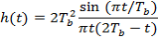 -- -- -- -- -- - ( 30 )
This impulse response is plotted in figure 4.8, which shows that it has three distinguishable degrees at the trying blink of an eyes.


Figure 4.8: Impulse response of modified duobinary transition filter
In order to extinguish the possibility of mistake extension in the modified duobinary system, we use a precoding process similar to that used for duobinary instance. Specifically, prior to the coevals of the modified duobinary signal, a modulo-2 logical add-on is used on signals 2TBseconds apart, as shown by
aK= BK+ ak-2modulo-2 -- -- -- -- -- - ( 31 )
Where { BK} is the input binary sequence and { aK} is the sequence at the precoder end product. Note that modulo-2 add-on and modulo-2 minus are same. The sequence { aK} therefore produce is so applied to the modified duobinary transition filter.
In instance of figure 4.6, the end product digit degree CelsiussKpeers 0, +2, or -2 Vs. Besides we find that BKcan be extracted from degree CelsiusKby ignoring the mutual opposition of degree CelsiusK, as was done with the duobinary technique. Specifically, we may pull out the original sequence { BK} at the receiving system utilizing the undermentioned determination regulation:

BK= Symbol 0 if |cK| & A ; lt ; 1 V
Symbol 1 if |cK| & A ; gt ; 1 V -- -- -- -- -- ( 32 )
- Generalized signifier of Correlative Coding


 The duobinary and modified duobinary techniques have correlativity spans of one binary figure and two binary figures, severally. It is consecutive frontward affair to generalise these two strategies to other strategies, which are known jointly as correlate cryptography strategies. This generalisation is shown in figure 4.9, where Hydrogendegree Celsiuss( degree Fahrenheit ) is defined in equation ( 18 ) .

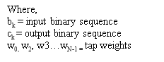

Figure 4.9: Generalized correlate cryptography strategy.
It involves the usage of a tapped hold line filter with tap weights tungsten0tungsten1, ,tungsten2, w3…wN-1.Specifically, a correlate sample degree CelsiusKis obtained from a ace place of N consecutive input sample values bK, as shown by
N-1
degree CelsiussK= ? tungstenNBk-n-- -- -- -- -- -- ( 33 )
n=0
Therefore by taking assorted combinations of whole number values for the tungstenN,we can obtain different signifiers of correlate coding strategies to accommodate single applications.
For illustration,
In duo-binary instance we have
tungsten0= +1
tungsten1= +1
and tungstenN= 0 for n?2.
In modified duo-binary instance we have
tungsten0= +1
tungsten1= 0
tungsten2= -1
and tungstenN= 0 for n?3.
Correlative cryptography is an efficient transmittal technique on bandlimited digital communications. Correlative cryptography introduces memory or correlativity to the transmitted informations watercourse in clip Domain, in a manner that the power spectrum of the transmitted bandlimited signal is shaped to exhibit gradual roll-off to band borders. This spectral belongings dramatically reduces the sum of inordinate intersymbol intervention at the receiving system when the symbol timing is non absolutely synchronized.
Particularly, correlatively coded OFDM has been widely used to supply high grade of hardiness against deep slices, and is much more popularly known as pre-coded OFDM. Despite these abundant applications, correlate cryptography is ne'er used in OFDM for spectral defining. Correlative cryptography is adopted to determine the signal spectrum of the rectangular pulsed OFDM signals with an effort to accomplish high spectral concentration.
Chapter 5
RESULT ANALYSIS
Matrix Laboratory [ MATLAB ] is a imitating tool which is used to demo all the consequences. As we have discussed in the old subdivisions, ab initio we will bring forth an OFDM signal and look into the sidelobe degrees for the generated OFDM. An OFDM signal is generated for the figure of bearersNitrogenas 128 and using a BPSK transition strategy for transition.
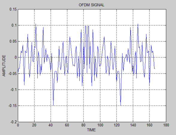
Figure 5.1: The generated OFDM signal
The power spectrum methods like Periodogram and Welch’s method were ab initio carried out for spectral appraisal but the consequences of which were non satisfactory. So Multitaper spectral appraisal technique was used to bring forth the power spectrum of the OFDM signal.
As we discussed in item about the multitaper spectrum analysis in subdivision 2.4.2, the stairss has been followed and the spectrum of OFDM is generated utilizing MATLAB package. Figure 5.2 illustrate the spectrum of above generated OFDM.
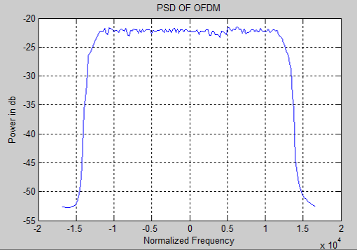
Figure 5.2: PSD of the generated OFDM.
As we discussed in the subdivision 4.1 and 4.2, the duobinry, modified duobinary cryptography is implemented. Figure 5.3 and 5.4 represent the duobinary coded OFDM and its PSD severally. Figure 5.5 and 5.6 represent the modified duobinary coded OFDM signal and its PSD severally.
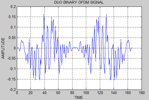
Figure 5.3: Duobinary coded OFDM signal.
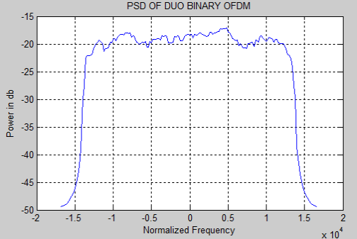
Figure 5.4: PSD of the duobinary coded OFDM signal.
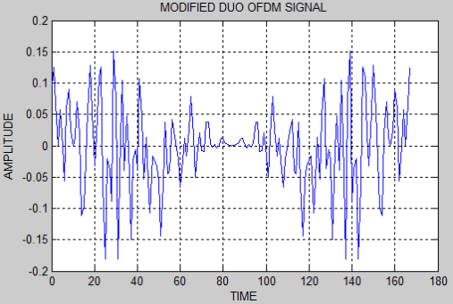
Figure 5.5: Modified duobinary coded OFDM signal.
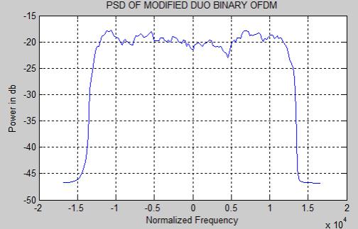
Figure 5.6: PSD of the modified duobinary coded OFDM signal.
The figure 5.7 will exemplify the PSD comparing of all 3 PSD’s in a individual graph as follows.
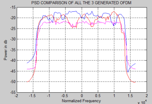
Figure 5.7: PSD comparing of OFDM, duobinary coded OFDM,
Modified duobinary coded OFDM.
1
